 |
Introduction to a Real Boiler System - continued.
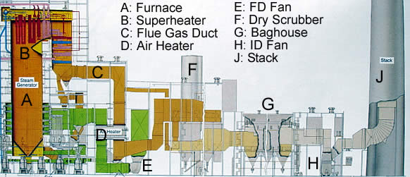
The graphic provided here illustrates an overview of a real 860 MW coal-fired utility boiler.
In the following pages, close-ups of various sections are provided with some brief comments. You are asked to get a good feel for the system presented here, by viewing the detailed sections, and then coming back to this page to see how they fit in the overall picture. Let’s identify the key sections illustrated in the graphic.
A. This is the main furnace region. Notice the green sections at the lower end of the main furnace cavity. The green regions connected to the furnace cavity represent ducting for the incoming combustion air and the burners.
B. This is the upper part of the furnace cavity. Flue gas is generated in the region A (due to combustion) and flows upward to region B. This section contains some of the superheater sections.