 |
Lubrication Systems
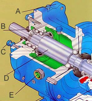
The figure provided here illustrates how lubrication is provided to bearings supporting a centrifugal pump shaft.
Important components shown in this figure are:
A. Antifriction (Ball) Bearings.
B. Lubricant Chamber. This chamber is used as a lube oil reservoir. The lower part of the bearings is in contact with the reservoir oil. As the bearings rotate, lubricating oil is taken up and spread in all regions of the bearings.
C. Sight Glass. This sight glass is used to monitor the oil level in the reservoir. Usually it is recommended that the oil level be maintained about halfway up in the sight glass.
D. Oil Seals. These seals are located on both sides and are designed to protect against leakage of oil along the shaft.
E. Breather. This connection is used for oil filling as well as the mounting point for the breather. The purpose of a breather is to allow air to enter and leave the oil reservoir. The temperature of the oil changes according to the operational conditions. As the air inside the oil reservoir gets hot, it expands. The breather allows the hot air to leave the chamber. On the other hand, when oil gets cold (for example, under shut down conditions), the air contracts and atmospheric air is sucked in. The problem is the atmospheric air contains dust and moisture, both of which are very detrimental to the lubricating oil. Most of the breathers are provided with an air dryer and a filter to ensure moisture or dust does not enter the oil reservoir.
G. Rotating Shaft.