Line Shaft PumpsIn this design, the lower part of the pump is submerged in water. Water is drawn in at the lower end of the assembly and flows upward through the column. Eventually water is discharged at the top of the column. This design consists of the following major components: a. Discharge Head It is the top part of the pump, indicated by “A” in the diagram. On the right hand side of this section you can see the discharge pipe. The discharge head contains a stuffing box. The stuffing box may contain packing material or a mechanical seal. The purpose of the stuffing box is to prevent leakage from around the drive shaft. |
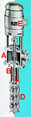 |
b. Column
This is the vertical section (B) located below the discharge head. The column contains bearings, installed at suitable intervals. The purpose of the bearings is to keep the shaft in alignment.
c. Drive Shaft
This long shaft (C) connects the motor rotor to the pump impeller. Usually, to reduce weight, the shafts are constructed with hollow pipes. It is indicated by “C” in the illustration.
d. Pump Section
This section contains the pump bowl assemblies which house the pump impellers. It is shown by D in the illustration. Notice the multistage design for the pump shown here.
e. Pump Motor
This refers to the electric motor (E) that runs the pump.