 |
Split Case Pumps
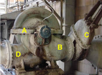
In this type of pumps, the volute case is horizontally split. In the figure, "A" indicates the split casing flange bolts. The suction side is indicated by "B"; the suction isolation valve is indicated by "C." Note that the suction side piping leads to the center of the pump. The discharge side is indicated by "D." Notice that the discharge piping extends from the circumferential region of the pump casing.
The incoming water enters the pump perpendicular to the drive shaft. Since the impeller eye is parallel to the pump shaft, the incoming water is turned through 90 degrees so that it can enter the eye of the impeller. When water enters the impeller eye, its direction is parallel to the pump shaft. The pump can be designed to accept suction at one or both sides of the impeller. If suction is accepted only on one side, the pump is referred to as a single-suction pump. On the other hand, if the pump can accept suction at both of its ends, it is referred to as a double suction pump.
For this type of pumps, it is very easy to remove the top half of the volute case, exposing all of the inner components. Usually these pumps are provided with a fully enclosed impeller. A picture of a fully enclosed impeller is provided in the following pages.
The pump shaft in this design is supported on both sides of the pump and is lubricated at both ends. These pumps are usually operated at relatively slow rpm (less than 1800 rpm). The additional shaft support and low operating speed results in high life expectancy for such pumps.
These pumps are normally much more expensive than ordinary centrifugal pumps.