 |
Packing (also called Mechanical Packing)
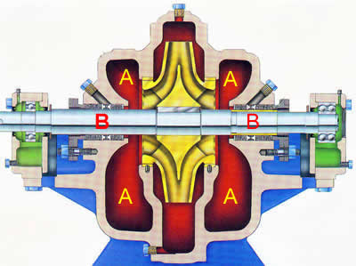
Consider the figure provided here. This figure illustrates a sectional view of a double suction centrifugal pump. The right hand side shows one end of the shaft, being supported by a roller bearing. The pump shaft leaves the pump body on the left hand side and is connected to a prime mover - the prime mover is not shown in this graphic. Notice as the pump shaft leaves the pump body on the left hand side it is supported by roller bearing as well - thus the pump rotor is supported on both sides with roller bearings. Now notice that, on both sides, the shaft is exposed to the environment in the region between the pump body and the roller bearings. If the fluid being pumped leaks along the shaft it will enter these two exposed regions.
In the figure, please note the following:
“A” shows the wet regions inside the pump. From these regions, water can leak out along the shaft.
“B” indicates the regions of the shaft where a seal is provided to prevent water from leaking out along the shaft. Notice the seal surrounding the shaft.